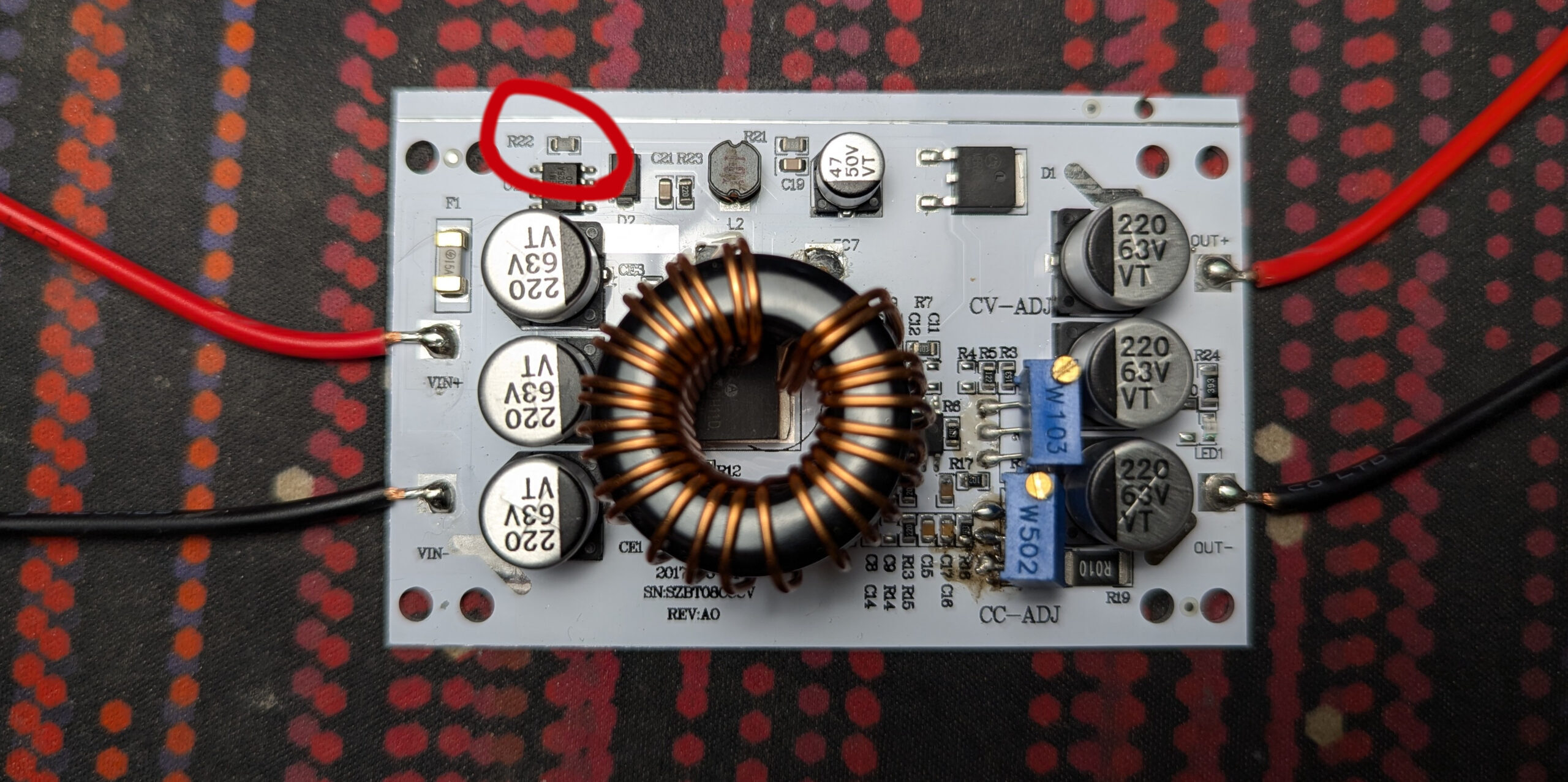
Just a quick article so this knowledge isn’t lost. This is specifically for the “white version” pictured but it should work for any one of these that uses an XL7005A as a startup(?) regulator. The board calls itself SZBT08CCCV. There is a smaller version that does not feature the same layout so don’t get that one!
The rest of the circuit uses a TL494 to do the constant voltage and constant current functions. As far as I can tell, the XL7005A is just there to be a fixed 13.5v rail to provide VCC for the main regulator and the mosfet gates.

Here is the schematic for a similar regulator which I found on this thread. There is some back and forth on whether it’s entirely accurate but it’s close enough for my purposes. The idea is to get at the enable pin on that XL7005A in order to shut it off. It’s active low and has a pull up resistor(R21 on the white module) and a pull down resistor(R22).
If we remove R22, the regulator shuts down. I have replaced R22 with an optocoupler but any type of transistor should do. Here is the revised schematic.

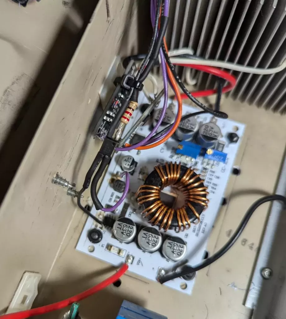
You can of course run the LED side of the optocoupler however you wish, I chose a 220 ohm resistor and an arduino pin but anything will work. Just make sure to choose a resistor that matches your control voltage. Here is a photo of the completed mod.


