This is going to be a quick write-up because I don’t expect anyone to do this the exact same way I did. The 8-Ball was meant to be a quick shitpost project to prove to myself that I can still do projects just for fun and not try to constantly monetize my hobby. All of the files are in the process of being released open-source(see links at the bottom).
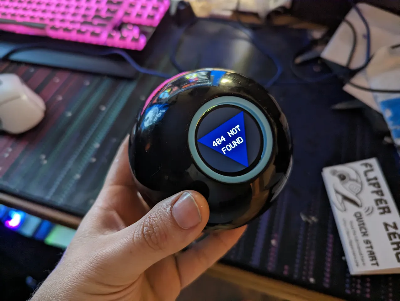
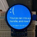
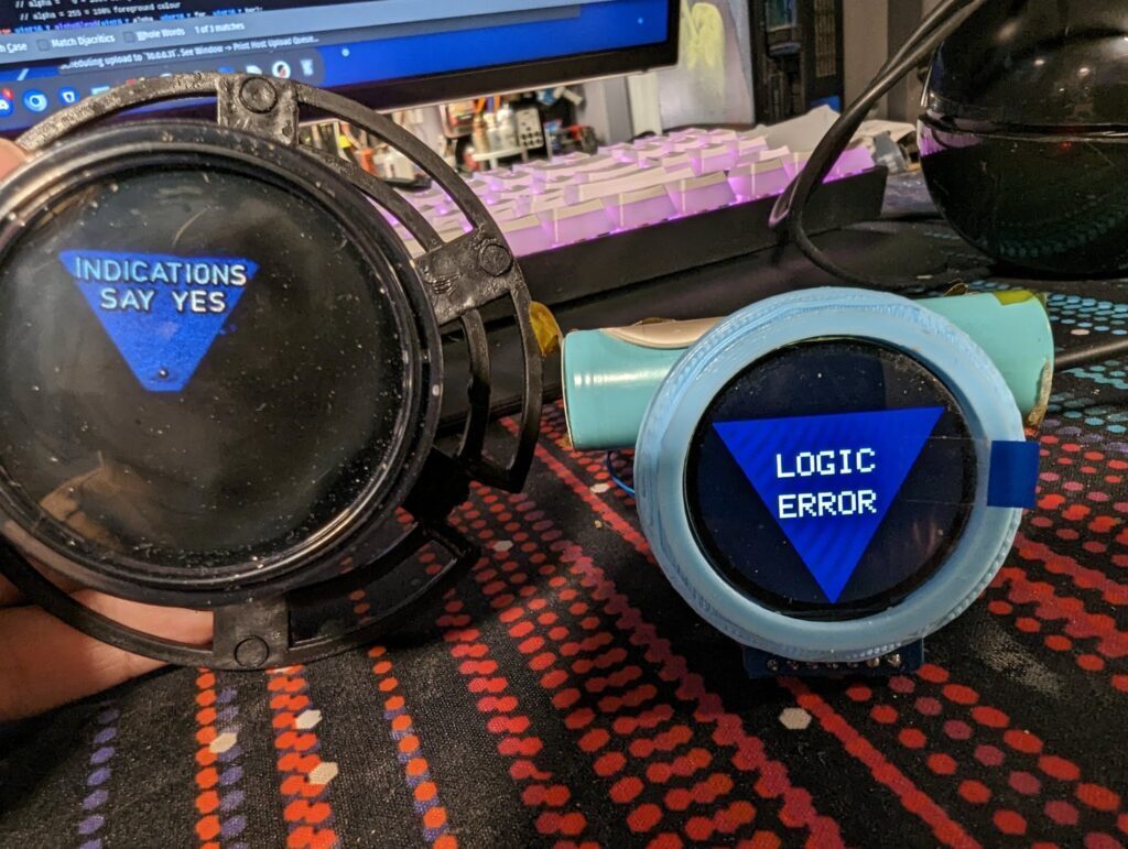
For some reason, a few months ago, I thought that it would be funny to have a Magic 8-Ball that quotes Dril tweets when shaken. I got to the prototype stage before I realized that I am chronically online and that no one else would find it funny if they shook the 8 ball and were told a random non-sequitur. After chatting with a friend, it was decided that giving bad tech-support advice was funnier.
Build Notes
I had initially thought a standard 128×64 OLED would be good for this project, but then I saw these round LCDs and fell in love. They are almost exactly the same size as the hole in the 8-Ball, leaving just enough space for a 3d printed bezel. They run down to 3.3v, have a built in regulator, and are connected over SPI so there aren’t too many wires. There are a few libraries to choose from, including an unofficial one from PaintYourDragon that is compatible with Adafruit’s Arduino GFX library. The one you should use on any 32 bit microcontroller is TFT_eSPI which is available in the arduino libraries manager.
The rest of the hardware in my case was simple:
- STM32F103C8 “Blue Pill” board
- Adafruit LSM9DS1(to detect shaking)
- 18650s and a TP4056 lithium charging/protection board
I chose the hardware before even attempting to open the ball, and I chose most of it because I had it laying around.
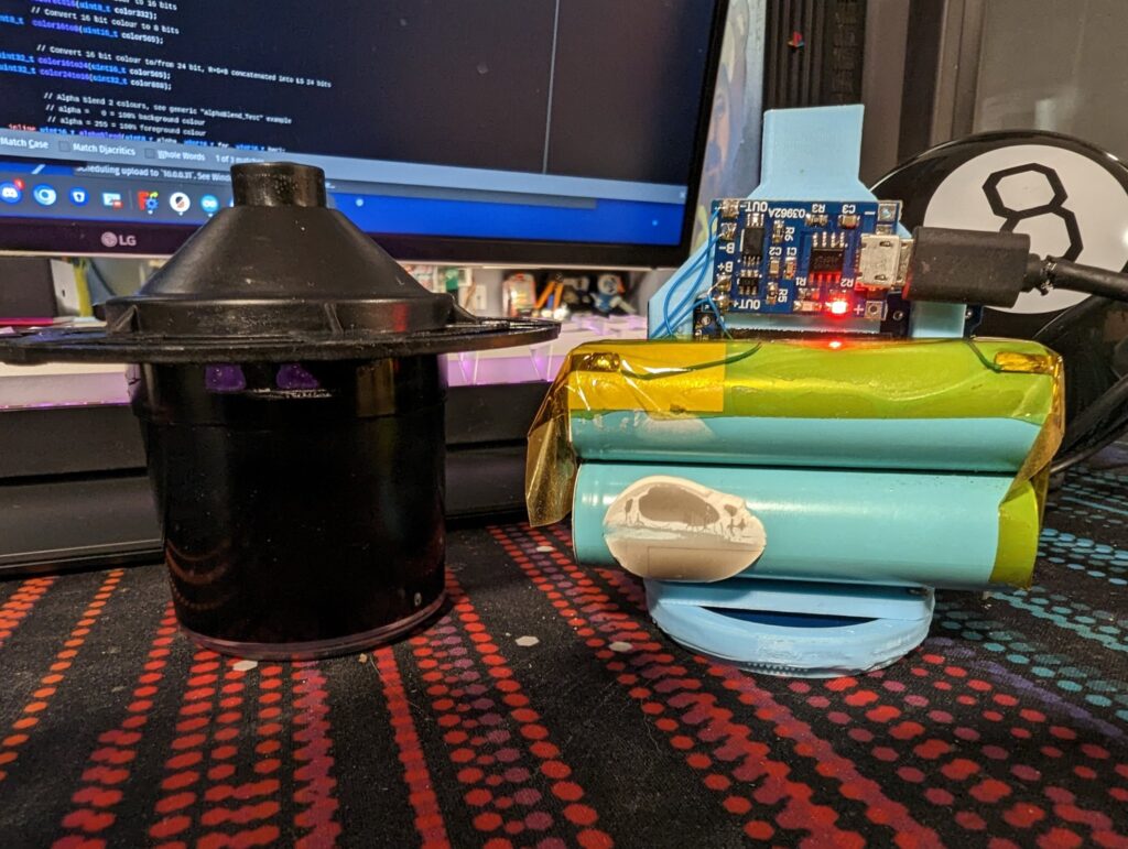
Cutting open the ball was nerve wracking but simple. I used a hacksaw to carefully split the ball in twain. It was not too thick and took about 5 minutes. Getting the ball back together in a way where it can be taken apart for charging was required some thought. I eventually settled on a friction fit with some electrical tape wrapped around a 3d printed ring.
Speaking of 3D printing, The most interesting part of this project is the sled itself. It was designed to mimic the shape of the fluid tank assembly that came with the ball. There is a carefully designed cavity to cradle the display, and a big platform for zip-tying all of the other junk to.
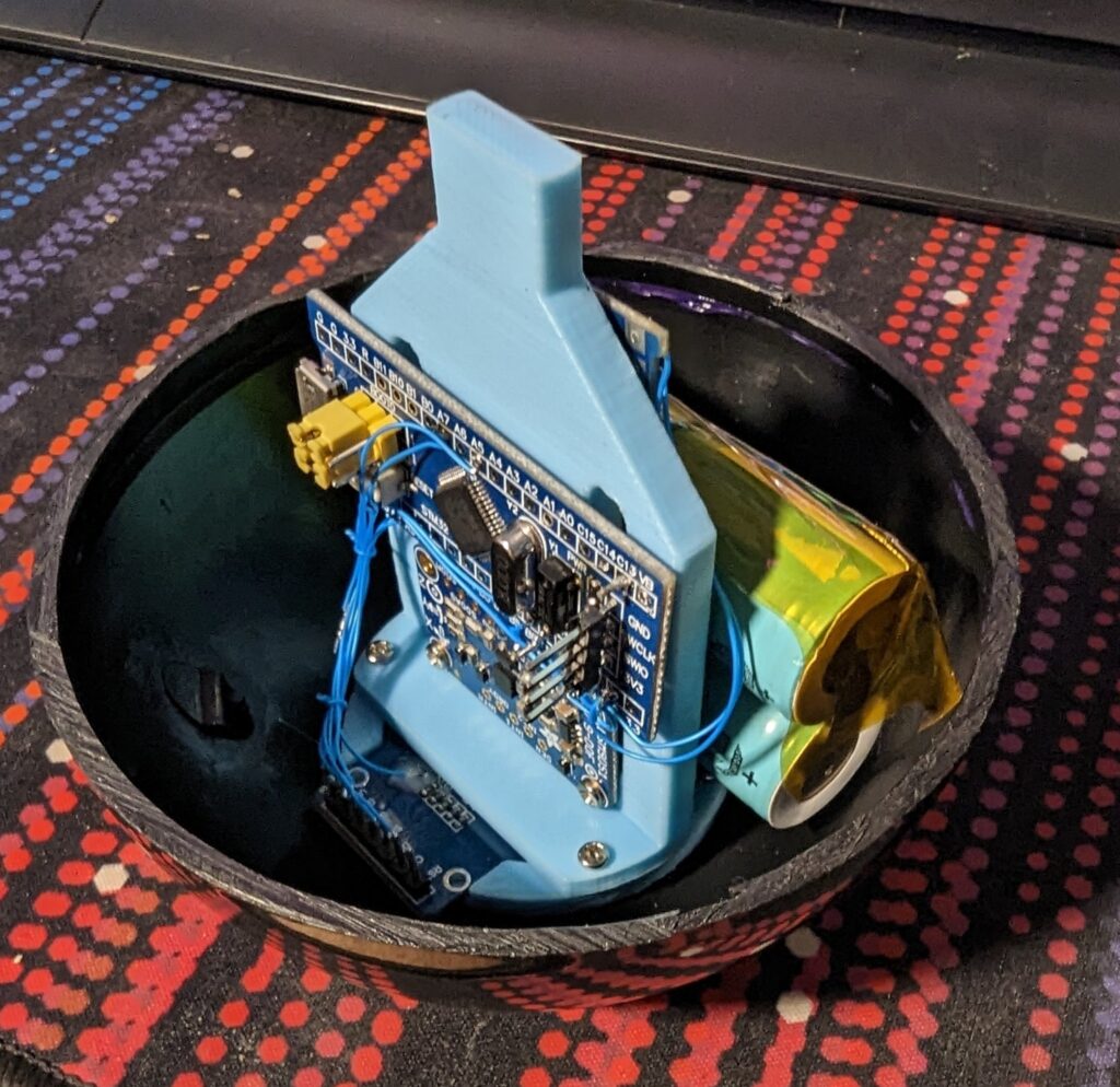
The wiring is pretty simple, i2c to i2c pins, spi to the spi pins, choose some random pins for backlight control and chip select.
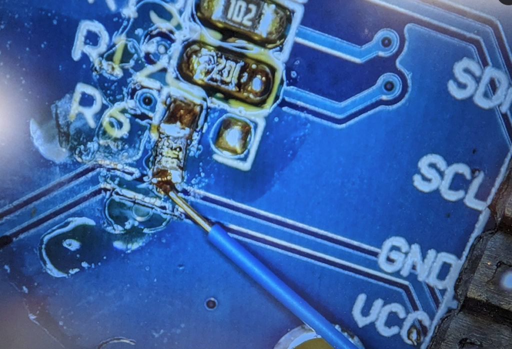
Oh yeah, backlight control! this display didn’t have that, it needed a quick little mod to enable that. Just gotta rotate R6 off of the gnd pad here and solder a wire to it. It can be directly driven by a 3.3v microcontroller pin. Here’s an ugly photo:
Powering everything was easy but it’s not exactly optimal. All 3 of the boards have their own LDO regulator and I decided that while I could get away with just using the one on the blue pill itself, it would be easier not to have to bypass the regulators on the daughterboards and it could cause problems with the accelerometer. One counterintuitive thing is that the battery is hooked directly to the 5v pin of the blue pill board. This isn’t exactly great, but since the STM32 itself runs at 3.3v, it was the easiest way to run the thing from the battery voltage which could be up to 4.4v
The final thing I want to talk about is power saving. You already know I modified the LCD backlight so it could be turned off when the ball was idle. The biggest power draw after that was the power indicator LED on the blue pill itself, so I pulled that off too(the number of smd components in my brass wool tip cleaner is astronomical). This left the screen-on current around 30ma and the screen-off current at somewhere around 13ma. That was fine, but remember we just disabled the backlight, the screen itself has a power save mode that blanks the LCD and turns off the charge pumps. Frustratingly, neither PaintYourDragon’s library nor the TFT_eSPI library support this power saving feature.
Luckily, the sleep mode can be accessed by sending a hex 0x10 with TFT_eSPI’s built-in writecommand() method. It can be woken up again by sending 0x11. There are some timing requirements in the datasheet, but nothing too stringent.
The final power saving measure was using STM32Duino’s Low Power library to put the microcontroller into deep sleep when the ball is inverted, waking up every second or so to poll the accelerometer to see if the z accelleraton has gone positive.
Conclusion
This was not really meant to be a tutorial, just an explanation of how I solved the hard problems with this project. As always I can be contacted via email or Twitter/Mastodon if you’re interested in discussing it in any detail. I’ll release the source code once I clean up the state machine and get the shake detection working reliably.
And hey, pop into my Mastodon/Twitter thread and ask the 8 Ball a question!
Parts and Links
- GC9A01 Round Display
- GC9A01 Adafruit compatible library
- TFT_eSPI library
- Cad Files
- 8 Ball
- TP4056 Module
- Software soon…
Here is the build thread on twitter:
3 responses to “Magic LCD 8 Ball for Tech Support”
Nice job! Enjoyed the build. I made a similar 8-ball using a steel sphere and some machined aluminum parts. ESP32 and similar GYRO/Accel. Used inverting the ball to activate the display message.
Mine answers all questions with, “How the F*ck Would I know?”
Anyways, great build.
Charles
[…] random answers and amusements. Combining new and old, Real-Time-Kodi was able to shoehorn a round LCD panel into a Magic 8 Ball where the floaty-answer display usually goes. It now provides answers to tech support […]
Hello! I was wondering if the source code was ever released?